Today, we will learn about GNSS sensors. With the continuous optimization and upgrading of RTK technology and the Beidou system, positioning accuracy has been increasingly improved, and applications have become more widespread. Mastering relevant knowledge is essential for hydrology professionals.
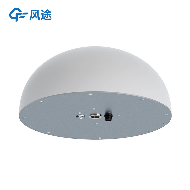
A GNSS sensor mainly consists of four parts: an upper cover, a lower cover, a protective ring, and a control panel.
The control panel includes several components:
Three indicator lights:
Satellite light (marked with a satellite icon): Glows green during operation. A steady green light indicates satellite lock, while a blinking light means loss of lock.
Status light (marked with a signal icon): Emits red and green light during operation. A steady green light indicates network connection, and slow red blinking means the receiver is sending or receiving data.
Power light (marked with a battery icon): Shows red and green light during operation. Blinking green indicates sufficient battery power, and blinking red means low battery.
[Fn] key (Function key): Used to set the working mode, data link, UHF radio channel, satellite elevation angle, sampling interval, and reset the receiver.
Power key: Turns the receiver on/off. It can also be used to confirm settings and query the current working mode.
8-pin data transmission interface: Connects the receiver to computers, data collectors, and external power supplies, facilitating the download and deletion of measurement data.
UHF radio antenna interface: Used to connect the built-in transmitting or receiving UHF radio antenna. However, this interface is only available on older receivers; most new receivers have a built-in antenna and no external interface.
Connection screw holes: Secure the device to a base or centering rod.
The protective ring has three protrusions, which are used to measure the antenna height.
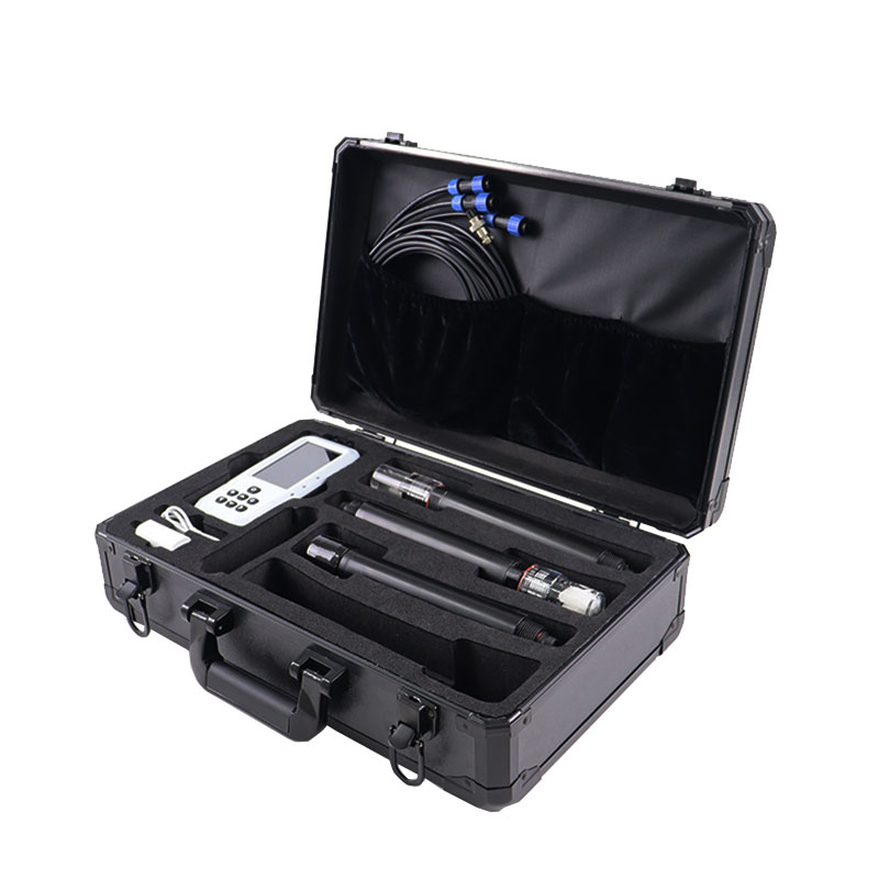
GNSS sensors are usually not used alone; they need to be paired with a centering rod or a tripod with a base. The assembly steps are as follows:
Assemble the receiver accessories, including installing the battery and UHF radio antenna (if applicable).
Tighten the assembled receiver to the centering rod via the connection screw holes.
Extend the centering rod to a certain angle and level it to complete the assembly.
A GNSS sensor has three working modes: Static, Base Station, and Rover Station. The operation steps are:
Power on: Press the power key for 1 second. All indicator lights turn on, and a startup sound and voice broadcast (announcing the current working mode and data link method) will play.
Control panel operation: Most settings and operations are completed using the two keys.
The [Fn] key is for selecting menu items and switching options.
The [Power] key is for confirming options.
Double-click the [Power] key to turn the LCD screen on/off. When activated, the screen displays the current working mode, satellite information, and version information.
Single-click the [Fn] key to automatically switch to the next option.
Single-click the [Power] key to enter the submenu.
Note: Icon information varies across different receivers, but all have text prompts. Settings should be adjusted based on the specific model—mainly confirming the working mode, selecting the data link method, and then setting parameters such as elevation angle, frequency, and port in the data link mode submenu.
Power off: Press and hold the power key for 3 seconds. All indicator lights turn off, accompanied by a shutdown sound.
After use, data can be exported via a data collector or data cable. The receiver must remain powered on during export; otherwise, the operation cannot be performed.
This paper addresses:https://www.fengtusz.com/industry/816.html